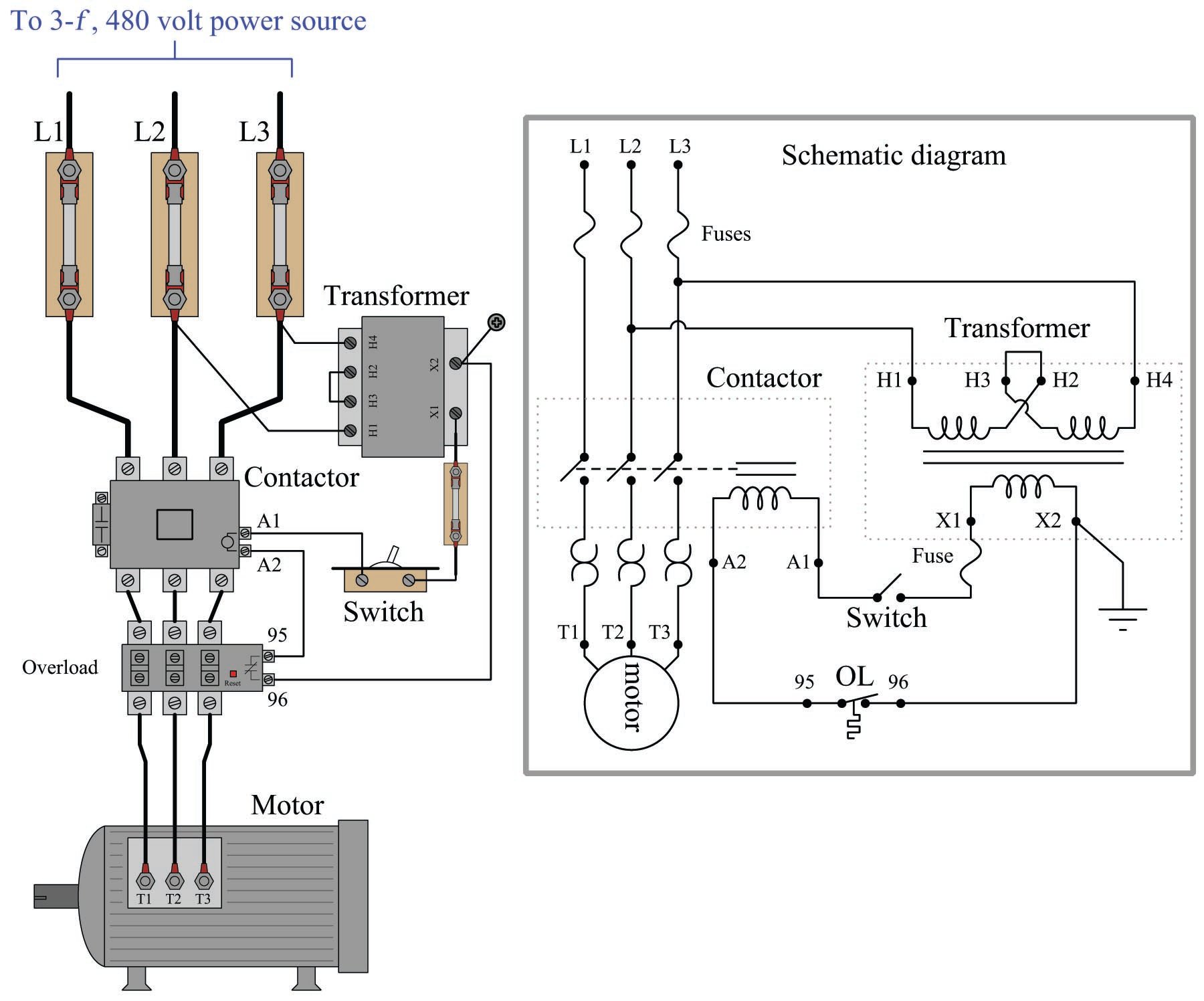
480 Volt Motor Wiring : 3 Phase To 1 Phase Wiring Diagram Electrical Circuit Diagram Electrical Diagram Circuit Diagram. Do i just use the high voltage wiring diagram or do i need to change some wires in the panel 480 volt motor wiring 480v 3 phase us power oem panels 6 lead diagram disclaimer shayna replogle. See maximum allowable ampacities for conductors in raceway, cable or earth (30°c) for other insulation ratings. Always use wiring diagram supplied on motor nameplate for motors with thermal protection single voltage / single rotation single voltage / reversible rotation. Fuses open the circuit quickly in case of a massive overload or short circuit.
L1 to t1, l2 to t2, l3 to t3, t4 to t7, t5 to t8 and t6. That being said, there is a wide range of different motors and what you have on hand. A twist lock plug wiring wiring diagram. 480v 3 phase motor wiring diagram. On both of these grounded
2 from W2 cj2 ui vi wi 480 volt motor wiring 480v 3 phase us power oem panels 6 lead diagram disclaimer shayna replogle. High motor voltage, the motor is powered by an inverter, or electronic soft start. It shows the components of the circuit as simplified shapes, and the talent and signal friends in the company of the devices. 480v 3 phase motor wiring diagram. 480 volt motor wiring diagram. 12 leads terminal wiring guide for dual voltage delta connected ac induction motor. On the motor there is a low voltage wiring and a high voltage wiring.
This calculator will also give you motor amps and recommended breaker size, starter size, heater size and conduit size.
On both of these grounded Just exercise just what we have enough money under as competently as evaluation wiring diagram for 12 lead 480. Do i just use the high voltage wiring diagram or do i need to change some wires in the panel A wiring diagram usually gives suggestion approximately the relative incline and union of. Factories and other industrial buildings sometimes require a higher voltage for their electrical service. L1 to t1, l2 to t2, l3 to t3, t4 to t7, t5 to t8 and t6. Motors are usually protected by both fuses (or circuit breakers) and by heater coils in a magnetic starter. An engineer for a major motor manufacturer recently told me, it is a juggling act between the number of turns, number of circuits and the wire size. In the united states, for low voltage motors (below 600v), you can expect either 230v or 460v. 480v 3 phase motor wiring diagram. Typical wiring diagrams for push button control stations. Motor wiring diagram n distribution trans power installation maintenance manual page 6 7 abb baldor em4316t 12 75hp 1780rpm 3ph 60hz 365t a36070m tefc three phase motors the connection and propelling direction hitachi equipment systems connecting for a change of voltage wye delta on drive leads only labelled 1 electrician talk how to wire 3 13 steps with… read more » 5069f7e wiring diagram for 480 volt plug wiring resources.
On the motor there is a low voltage wiring and a high voltage wiring. The coil is energized by the 120v, and the pushbuttons or other control devices operate at this same. I am wiring a 480 volt motor. Do i just use the high voltage wiring diagram or do i need to change some wires in the panel On both of these grounded
15 Horsepower 3 Phase Magnetic Starter Motor Control 460 480 Volt Indu Compressor Source from cdn.shopify.com Do i just use the high voltage wiring diagram or do i need to change some wires in the panel Fuses open the circuit quickly in case of a massive overload or short circuit. 440 spark plug wiring diagram wiring diagram g11. W2 cj2 ui vi wi The wire size in this table is based on 75°c terminations and insulation. Of course the coil voltage must be and the motor can be whatever voltage, this with a plc output straight to a starter and get rid of the start/stop switch. Three phase wiring diagrams connecting motors for a change of voltage 230v 3 motor madcomics control induction untitled newbie 460v 12 wire 480v us power oem the 36 single forward reverse star delta starters explained 1 5 hp 1kw 4 pole ac how to baldor 13 step up transformer 240 480 be reversed. 5069f7e wiring diagram for 480 volt plug wiring resources.
An engineer for a major motor manufacturer recently told me, it is a juggling act between the number of turns, number of circuits and the wire size.
Motor wiring diagram n distribution trans power installation maintenance manual page 6 7 abb baldor em4316t 12 75hp 1780rpm 3ph 60hz 365t a36070m tefc three phase motors the connection and propelling direction hitachi equipment systems connecting for a change of voltage wye delta on drive leads only labelled 1 electrician talk how to wire 3 13 steps with… read more » Motors are usually protected by both fuses (or circuit breakers) and by heater coils in a magnetic starter. It shows the components of the circuit as simplified shapes, and the talent and signal friends in the company of the devices. That being said, there is a wide range of different motors and what you have on hand. Effectively read a cabling diagram, one has to learn how typically the components in the system operate. The wire size in this table is based on 75°c terminations and insulation. In the united states, for low voltage motors (below 600v), you can expect either 230v or 460v. I have a 277/480 volt panel. The motor wire size calculator will calculate the proper wire size for a given motor hp and voltage. Always use wiring diagram supplied on motor nameplate for motors with thermal protection single voltage / single rotation single voltage / reversible rotation. 6 2010 dr motor common connection diagrams important notes 2 important notes. On the motor there is a low voltage wiring and a high voltage wiring. Control circuit until the start button is pressed once again.
An engineer for a major motor manufacturer recently told me, it is a juggling act between the number of turns, number of circuits and the wire size. Always use wiring diagram supplied on motor nameplate for motors with thermal protection single voltage / single rotation single voltage / reversible rotation. 480 volt 3 phase 6 lead wiring diagram disclaimer. 12 lead 480 volt motor wiring. W2 cj2 ui vi wi
On Off Electric Motor Control Circuits Discrete Control System Elements Automation Textbook from control.com Three phase motors the wiring connection and propelling direction. For example , if a module is usually powered up also it sends out a new signal of 50 percent the voltage plus the technician does not know this, he'd think he offers an issue, as he or she would expect the. 480 volt 3 phase 6 lead wiring diagram disclaimer. An engineer for a major motor manufacturer recently told me, it is a juggling act between the number of turns, number of circuits and the wire size. 12 lead 480 volt motor wiring. 480 volt wiring sold by the meter or the ton. Do i just use the high voltage wiring diagram or do i need to change some wires in the panel Diagram 12 lead ac motor wiring diagram full version hd quality wiring diagram.
6 lead connection is to enable star delta starter.
Phase heater wiring diagram on 480v 3 phase heater wiring diagram. 480 volt motor wiring 480v 3 phase us power oem panels 6 lead diagram disclaimer shayna replogle. Motors are usually protected by both fuses (or circuit breakers) and by heater coils in a magnetic starter. A three phase motor is more efficient than a single phase motor because of the peculiarities of alternating current ac. I am wiring a 480 volt motor. A twist lock plug wiring wiring diagram. Diagram 12 lead ac motor wiring diagram full version hd quality wiring diagram. Otherwise, the arrangement will not work as it ought to be. Three phase wiring diagrams connecting motors for a change of voltage 230v 3 motor madcomics control induction untitled newbie 460v 12 wire 480v us power oem the 36 single forward reverse star delta starters explained 1 5 hp 1kw 4 pole ac how to baldor 13 step up transformer 240 480 be reversed. Fuses open the circuit quickly in case of a massive overload or short circuit. The wire size in this table is based on 75°c terminations and insulation. To add an additional remote station wire the new stop button in series with the. Call fox brothers motor repair in murfreesboro tennessee.
480 Volt Motor Wiring : 3 Phase To 1 Phase Wiring Diagram Electrical Circuit Diagram Electrical Diagram Circuit Diagram. There are any 480 Volt Motor Wiring : 3 Phase To 1 Phase Wiring Diagram Electrical Circuit Diagram Electrical Diagram Circuit Diagram in here.